
The Ultimate Guide
to Internet Congestion Control
by Michael Schapira
Introduction
Congestion control is a complex topic, with decades of academic research around it. In fact, scientists still have heated debates about it to this very day. This ebook is intended to explain the core concepts and approaches of internet congestion control to non-experts. Of course, it’s possible to go into a lot more depth about it, and we have sprinkled some links to additional resources for further reading throughout this guide.
Today’s internet is a busy and crowded place. There are many different services and applications jostling each other to send their traffic over the same network infrastructure. Sometimes, there simply isn’t enough space for everyone.
Internet traffic is segmented into packets, which are individual units of data. When the network bandwidth can’t support the transmission of every packet of internet traffic, the network becomes congested. This is just like our physical highways that get choked with vehicles during rush hour.
The need for congestion control becomes obvious when the volume of traffic rises to overwhelming levels. An example would be during Super Bowl Sunday when everyone is online at once trying to watch the game. This also happens when the network capacity is too limited to support even a moderate amount of traffic, which can happen in remote or rural areas with restricted bandwidth. That said, congestion control is needed on a permanent basis. Because we’re all sharing the same network resources, with demand often far exceeding the supply, we need to share them in a reasonable way.
Internet congestion control brings order to this crowded traffic system by sharing bandwidth between users in an organized manner. In this way, everyone can enjoy a better quality of experience.
Section 1
What is internet congestion control and why does it matter?
What is internet congestion control and why does it matter?
Congestion control is all about controlling the rate at which data is sent by each traffic origin at any given point in time. In short, congestion control governs how the total network capacity is divided up among all those transmitting data. We need congestion control to prevent internet traffic from getting clogged and swamping the networks. Due to its complexity and crucial significance, congestion control is a perennial challenge for communication networks.
Congestion control vs. flow control
Before we dig deeper into congestion control, here’s a quick explanation of two terms that are sometimes confused: congestion control and flow control.
-
Flow control is concerned with preventing the sender from swamping the receiver with too much traffic. It's a fairly straightforward problem to solve; the receiver can simply tell the sender what speed of traffic it can cope with, and the sender adjusts its send rate accordingly.
-
Congestion control is about finding ways for traffic to efficiently utilize the network, and interact with competing traffic without overwhelming it. Networks are dynamic and offer limited visibility, leaving the sender to infer what is going on. This can be an extremely complicated undertaking, as you’ll see throughout this ebook.
Flow control has been a concern since the early days of the internet because the sending computer cannot transmit at a rate that is faster than what the recipient can receive. Congestion control only emerged as a serious issue in 1986, when the internet experienced its first “congestion collapse”.
The graph below shows the growth of users connected to the internet. (Yes, in 1969 there were only 4.) In 1986, when there were just 5,000 online users, the demand for bandwidth suddenly outstripped the supply. When the few-hop network path between Lawrence Berkeley Lab (LBL) and UC Berkeley became congested, the throughput dropped from its usual 32 Kbps to 40 bps (a 1000x decrease!). This was the historical trigger for the creation of internet congestion control algorithms.
Hobbes’ Internet Timeline Copyright @2006 Robert H Zakon
http://www.zakon.org/robert/internet/timeline

Figure 1: Hobbes’s Internet Timeline; constant increase in end-users and the emergence of congestion
Why we need congestion control
Our favorite analogy for explaining internet congestion control is that of water being pumped through a pipe, as you can see in Figure 2 below.

Figure 2: Water analogy explaining internet congestion control
If the water flow isn’t strong enough, it will take much too long for the end user to fill their bath. But, if there’s too much water, it could strain the pipe and cause leaks. Similarly, if data isn’t pumped through the network fast enough, the end user might not receive enough data to enjoy good quality of experience (QoE). For example, if someone is watching a movie in HD, they need a great deal of data coming in to get a clear and sharp picture.
If too much data is pumped into the pipe, the pipe might not be able to handle the volume. It could end up leaking data, a phenomenon called packet loss, causing the end user to get frustrated by repeated video re-buffering. So, sending data too fast can also cause poor QoE.
Congestion control needs to walk that fine line between not sending enough data, and sending too much data
Congestion control should not be confused with routing, another fundamental networking challenge. Going back to the water pipe analogy, while congestion control is tasked with ensuring that the pipe is used efficiently, routing is responsible for determining which pipe, or sequence of pipes, the water (data) will flow through. Internet routing algorithms determine which paths data traffic will traverse. In today’s internet, unlike its early predecessors, congestion control and routing are handled independently by separate algorithms.
The importance of congestion control for quality of experience
QoE refers to the level of satisfaction that data consumers experience when they use the internet. In the context of video streaming, for example, QoE is manifested in:
-
How long it takes your streaming video to begin to play.
-
Image quality, such as whether you can enjoy a movie in HD or in lower quality, or if you see a sudden drop in quality halfway through.
-
Rebuffering time, which is the amount of time you have to spend watching that dreaded wheel go round and round waiting for your video to resume. (Research has shown that people’s physical response to seeing the buffering wheel is similar to when they watch a horror movie.)
-
Latency (“time behind live”) refers to the time lag between the action and its appearance on your screen. This is a crucial issue for real-time sports broadcasting, where even a few seconds’ lag can lead to viewers hearing the cheers from neighboring apartments or seeing spoilers on social media, before they see the goal scored.
Congestion control is one of the factors that has the biggest impact on QoE for such services, far more than a faster internet connection.
Internet providers may claim that upgrading to 5G, fiber optic cables, or higher bandwidth will solve your QoE issues. These are often empty promises. According to research covered by The Wall Street Journal, even the highest bandwidth subscribers typically receive HD video only about 36% of the time.Consumers may be wasting their money on large internet packages, when the problem lies elsewhere.
The real problem for QoE is typically the “last mile” in which the data leaves the cloud or content delivery network (CDN) and arrives at the end user’s device. Different problems in data delivery often arise long before the data arrives at the consumer’s home. Therefore, broadening the home internet connection by ramping up its bandwidth is like widening the mouth of a narrow pipe. Water can’t run any faster through the rest of the pipe just because the mouth of the pipe is broader.
As shown below in Figure 3, CDNs go a long way towards making content delivery both faster and more reliable by using a network of proxy servers located around the world. The closer a CDN server is to the end consumer, the less time it takes for content to reach the consumer’s device. Nevertheless, no matter how small the distance, servers and users are still often separated by challenging network segments that the data must traverse. It’s worth noting that for non-cacheable content such as video conferencing, CDNs are no help at all.

Figure 3: Content delivery through network of proxy servers
Learn more about the importance of the last mile for QoE
This last mile is often a chaotic journey that can include multiple transfers between different networks (CDN, ISP, home) and network segments (mobile, wired, wireless, home WiFi). Each leg of this journey involves conditions that can continuously change from one moment to the next, making congestion control highly complex. Successful congestion control must simultaneously satisfy three different goals, which can be at odds with each other.
Section 2
The three goals of congestion control
The three goals of congestion control
The three goals of successful congestion control are:
-
Make the most of network bandwidth
-
Keep data-loss and delays to a minimum
-
Be fair across all connections
There is a definite trade-off between these three goals. Although you want to fully exploit the network bandwidth, you don’t want to overshoot because that leads to data loss. You could prioritize fairness at all costs, but this may lead you to underutilize the network bandwidth.
You can’t fully solve congestion control unless you address each one of these goals. Here’s a more in-depth explanation.
Imagine a simple scenario, like the one in Figure 4 below showing three connecting pairs:

Figure 4: Multiple traffic flows sharing a link
Typically, internet connections are two-way. Facebook, for example, sends data to end-users, but these end-users also send data back to Facebook. Each sender is also a receiver and vice versa. To simplify things, we’re imagining that in all three connections, one end-point (the sender) is sending traffic to the other end-point (the receiver). Specifically:
-
A Facebook server (Sender 1) sends traffic to a Facebook user (Receiver 1)
-
A Netflix server (Sender 2) sends traffic to a Netflix video client (Receiver 2)
-
A Zoom video conferencing user (Sender 3) sends traffic to a different Zoom user (Receiver 3)
Let’s say the three senders share a network link that has a bandwidth of 120 Mbps, which means that it can deliver 120 megabits (120,000,000 bits) of data per second.
What data-transmission rates should the three connections use? That’s exactly what the congestion control algorithm must determine. Here are the ways our three congestion control goals affect the algorithm’s outcome.
Make the most of network bandwidth
Internet services and applications often want to send data at the highest possible rate, because that translates into better QoE for the user. Therefore, congestion control should make it possible for applications to use as much bandwidth as they have available.
In our example, we have a bandwidth of 120 Mbps. The algorithm could allow each connection to use 10 Mbps, but that would mean that together they are only using 30 of the available 120 Mbps. That leaves a lot of spare bandwidth waiting around, unused. It also means that the applications might be restricted to a lower bandwidth than necessary for good QoE. So, ideally, together, the three senders should inject traffic at a rate of 120 Mbps, thus fully utilizing the link.
Keep packet loss and delay to a minimum
When data packets enter the network faster than the network can support, that creates congestion, and congestion can cause packet delay and/or loss.
Imagine, for example, that each application transmits data at a constant rate of 60 Mbps. Their total transmission rate would be 3 x 60 = 180 Mbps, which is 50% above the network bandwidth.
That’s a problem. The network can’t send all the data packets as soon as they enter the network because there are simply too many. The network stores (buffers) the extra data packets at Router A until it can send them onwards. This causes delays in data arriving at the receiver and may even lead to data being discarded and lost if there is not enough room to store it within the network.
Be fair across connections
The last requirement is that the algorithm has to treat all senders fairly. When it comes to congestion control, it can be difficult to define what “fair” means in general. For our simple example, we’re going to say that “fair” means every sender can transmit data at the same average rate. If Facebook can send data at 80 Mbps, but Netflix and Zoom can only send data at 20 Mbps, that’s not very fair to Netflix and Zoom, or the people using those apps.
To solve for all 3 goals, we could say that each sender should transmit data at 40 Mbps. This seems like the perfect solution and it resolves all 3 requirements:
-
Make the most of network bandwidth. Total network usage is 120 Mbps, which is 100% of capacity and ensures that no extra bandwidth gets wasted.
-
Keep packet loss and delay to a minimum. Traffic doesn’t enter the link any faster than the network can handle, so there’s no unnecessary packet delay or packet loss.
-
Be fair across connections. Each of the senders use exactly the same share of bandwidth.
It appears deceptively simple. So why is congestion control such a complex challenge? It’s because the real world of internet traffic is far more complicated than our simple example.
In real-world internet congestion control, each of these senders makes decisions independently of the others. This is done without much information about conditions within the network, such as the link capacity, and the network conditions are constantly changing. What’s more, there can be far more than three connections competing for network bandwidth, with new connections unexpectedly entering the network while others abruptly leave.
We discuss this in more detail in the next section.
Section 3
Why is internet congestion control so challenging?
(Hint: Because the real world is complex)
Why is internet congestion control so challenging?
(Hint: Because the real world is complex)
Congestion control is one of the most enduring and critical problems addressed in networking research and practice.
The main issues handicapping internet congestion control solutions are all present in the challenging “last mile,” where:
-
Network conditions can vary dramatically and rapidly change over time
-
Traffic rate decisions are decentralized
-
Traffic senders have very limited information about network conditions
-
Different connections compete over network bandwidth
-
Internet applications and services that share the same network have varied and conflicting demands
Highly variable network conditions
Last-mile networks are often complex, diverse, and dynamic environments. Different network segments can vary in size, structure, loss pattern, network latency, level of competition, and more. Think of it as a large, chaotic tangle of pipelines, where some of them are large and broad, while others are narrow, leaky, and twisted.
The daunting diversity of network conditions can be illustrated even using our simple example in Figure 4. Network properties include:
-
The bandwidth of the network link
-
The time it takes data packets to cross the link (aka the link latency)
-
The size of the buffer used by Router A to store excess data packets when the link capacity is exhausted
-
The queuing policy that Router A uses to discard packets when it reaches full buffer capacity
-
And more
All of these properties have significant implications when it comes to congestion control. For example, if the network queue, or buffer, is shallow, then overshooting bandwidth by even a small amount can cause packet loss. But if the queue is deep, overshooting bandwidth could result in packets being aggregated within the network to be sent when congestion eases again, leading to long delays.
In addition, the amount of data traveling through these pipes changes constantly. From one second to the next, different volumes of traffic jostle for the same stretch of pipes. Moreover, some of the pipes themselves can present challenging conditions, such as mobile networks or satellite networks, which are prone to losses. In such networks, packet losses experienced by connections may not be due to congestion at all, but to other reasons, like the physical medium or user mobility. Uncertainty about the network conditions makes it difficult to reach informed decisions about the current sending rate.
Sending rate decisions are decentralized
Currently, each sender makes its own independent decisions regarding the rate to use when sending data packets. There’s no central body overseeing these decisions, and no obvious way for any given sender to know which rates are being used by competing senders, or even how many other senders are competing with it over network bandwidth. As much as we hope that rate decisions will interact well with each other, there’s no way to ensure this.
Limited feedback about transmission success and failure
The problem is compounded by the fact that the sender has very limited visibility into the network itself. With the exception of very specific network environments (like data centers), internet networks and, in particular, last mile networks, don’t provide any direct feedback to the sender. The only feedback you’ll see in a last mile environment is endpoint feedback, between the end receiver and the sender.
It’s a lot like trying to understand what’s happening in an unseen network of water pipes. You know that the water has left the water company’s reservoir, but you have no idea what happens as it travels through different pipes on its way to the user’s bathtub. There could be a burst water main, too much flow when water enters a smaller pipe, or a series of leaks in the end user’s home piping. Any of these can cause the user to have trouble filling a bath. It’s also possible that someone else in the house is diverting water by washing dishes at the same time.
Sending traffic across internet networks is similar in many ways. The sender doesn’t know what happens to its data en route to the user, only whether or not the data ultimately reached the user (and sometimes they don’t even know that). If data gets lost or delayed on the way, no one knows exactly why this happened.
Competition between connections
When multiple connections interact on the same network, as in our previous example, the dynamic behavior of one sender can significantly impact other senders. In Figure 4, we showed three pairs of users connecting over the same network. If Sender 1 instantly decides to significantly increase its transmission rate, this can result in congestion, leading to packet loss for all three senders. Alternatively, if a sender’s transmission suddenly terminates, network bandwidth will instantly free up for use by the other connections. Senders have no way of explicitly knowing which other senders are using or have stopped using the network, but need to act efficiently despite this lack of information.
It gets even more complex. There are already a number of congestion control solutions out there, such as TCP Cubic and BBR. Any new congestion control solution must coexist alongside other solutions, which muddy the waters even more, adding further uncertainty about the network environment. Any new congestion control algorithm still needs to be fair to connections that use different congestion control solutions. It’s unfair to use a congestion control solution that is overly aggressive to connections using other algorithms (we’re looking at you, BBR), and drags down their performance.
Internet services with varied and conflicting demands
There are still more issues to consider in this chaotic mix of factors. Internet services and applications can have different requirements in terms of bandwidth and latency. Services such as real-time video streaming; augmented, virtual, or mixed reality; and broadband IoT, all have different requirements. Sometimes, it’s not possible to meet all of them at the same time.
Think about our first example in Figure 4, in which Facebook, Netflix, and Zoom are all sharing a single connection link. Each application wants “good QoE” for its users, but they each have a different definition of “good”.
For video on demand like Netflix, it’s essential to have high bandwidth that supports HD viewing, so the picture is always clear and sharp for the viewer. If there’s a fairly small, consistent lag in video delivery, it won’t inconvenience the viewer.
Zoom video conferencing needs low latency above all else, to prevent a time lag when different people are speaking. Even a half-second delay can cause participants to talk over each other and miss important parts of the conversation.
Internet applications also differ in how time-sensitive they are. Imagine that your smartphone downloads a software update while you’re streaming a movie. Clearly, the movie is time sensitive, and should be given higher priority for bandwidth while it’s playing. You’d probably be perfectly happy to have the software update take longer if that kept your movie from being disrupted, having to rebuffer, or being displayed in lower definition instead of HD.
The diversity of application requirements means that it’s not always clear how network bandwidth should be partitioned. This can be explained by a fable about a camel and a zebra that cross the desert together. They have a limited amount of water, so to be fair they agree that they’ll each drink the same amount. By the time they reach an oasis, the zebra has almost collapsed from dehydration, but the camel has barely touched its water. Like the zebra and the camel, different internet services have different needs, and treating them according to an artificial standard of “equality” is sometimes undesirable.
Section 4
Introducing TCP
Introducing TCP
The Transmission Control Protocol (TCP) is a popular congestion control solution dating back to the earliest days of the internet. It relies on data packet feedback to work out the best data transmission rate. We now explain how TCP congestion control works.
TCP relies on data packet feedback
In our example in Figure 4, each sender transmits packets of data and receives feedback about whether or not the packet arrived. This feedback is in the form of an acknowledgement (ACK) that is sent when a packet is received.
Although this feedback is quite limited, senders can still derive valuable information by examining ACKs, to track which packets weren’t received and how long it takes data to traverse the network. Specifically, the loss of a packet can be inferred when enough time has passed for the packet to reach its destination but an ACK was never received. A loss can also be deduced when ACKS are received for subsequent packets but no news arrived from the receiver about the fate of this packet. In addition, network delay can be estimated by examining how long it takes an ACK for a sent packet to arrive at the sender. The time that passes between the transmission of a packet and the return of an ACK for that same packet is called its round-trip-time (RTT).
The TCP congestion window
A key concept in TCP congestion control is that of a congestion window. A congestion window is the maximum permissible number of packets that can be en route (or “in flight”) from the sender to the receiver at any given time. Once the packet arrives at the receiver and the sender gets an ACK, the packet has arrived and is no longer “in flight.” Actually, the congestion window specifies the number of bytes of data that can be “in flight” at any given time, but for simplicity we will think of it in terms of the number of packets.
Figure 5 below illustrates the concept of a congestion window. Imagine the congestion window is 10 packets. If the sender already sent 4 packets, it can still send another 6 while waiting for the first 4 to arrive at its destination. But if the sender sent 10 packets, it can’t send another packet until it receives an ACK indicating that a packet has arrived at the receiver. Otherwise, the sender would exceed the number of packets that can be in flight.
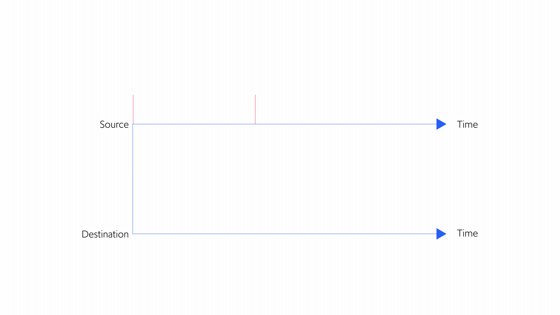
Figure 5: Concept of a congestion window
adapted from http://gaia.cs.umass.edu/kurose-ross-ppt-6e/
TCP controls the size of the congestion window. The larger the congestion window, the more data packets can be traveling to the receiver at the same time; this translates into sending traffic at a faster rate. TCP congestion control is all about adjusting the size of the congestion window over time. If the congestion window is too large, the rate at which packets are sent will exceed the network capacity, resulting in packet losses and/or delays. If the congestion window is too small, traffic might be sent too slowly for good quality of experience.
Note that TCP does not explicitly change the sending rate. In other words, a TCP sender does not make decisions in the form of “change the sending rate to 7 Mbps.” Instead, sending rates are changed indirectly through changes to the congestion window. For instance, if the window size is 100, the size of each packet is 4000 bits, and the RTT is 1 second, then, on average, the sending rate is (100x4000)/1 = 400,000 bps = 0.4 Mbps.
We will revisit this point later when we discuss alternatives to TCP congestion control.
How TCP works: slow start and congestion avoidance
TCP begins by setting the congestion window to be very small and doubling it every RTT. This phase is called “slow start”. It continues until the TCP connection runs into difficulties, for instance, in the form of packet losses, or when the congestion window exceeds a certain threshold. When slow start is terminated, the connection enters the “congestion avoidance” phase. During congestion avoidance, the size of the congestion window increases upon the successful receipt of an ACK, and is decreased when packet loss is detected.
TCP Reno's slow start during the first 20 seconds, followed by congestion avoidance, is shown in Figure 6. TCP Reno is the classic variant of TCP proposed in 1990. Suppose a sender using TCP Reno is alone on a link. When in congestion-avoidance mode, the sender will increase its congestion window size as long as no packets are lost and ACKs for the sent packets continue arriving at the sender. The increase in window size for each received ACK is modest, to avoid overshooting network capacity.
At some point, the sending rate will exceed the link capacity, the link's buffer will reach its saturation point, and packets will be lost. When that happens, TCP Reno will cut the congestion window size in half. This gives rise to Reno’s famous “sawtooth” behavior, seen below. Here, the sender reaches link capacity, sees packet loss, and then plummets back down before restarting its ascent. This form of behavior, in which the congestion window is increased by a fixed additive factor when an ACK is received and is decreased by a multiplicative factor when packet loss is detected is termed Additive-Increase-Multiplicative-Decrease (AIMD for short). TCP Reno can also drag traffic rates back down to a slow start if it doesn’t receive any feedback for a while.

Figure 6: TCP Reno's slow start and sawtooth behavior
Adapted from Figure 7 in https://blog.apnic.net/2017/05/09/bbr-new-kid-tcp-block/
TCP convergence and fairness for multiple senders
When multiple TCP senders share the same network bandwidth, they must continuously react to each other’s sending rates, without actually knowing what those rates are.
Imagine that two senders are sharing the same network link, as in Figure 7 below, and that the link capacity is R Mbps.

Figure 7: Senders sharing bandwidth on the same network link.
Adapted from http://gaia.cs.umass.edu/kurose-ross-ppt-6e/
Ideally, both senders share the bandwidth equally over time, like two equal streams of water flowing through a pipe, rather than one stream taking over the entire pipe and leaving no room for other water flow. But that’s difficult to achieve, especially without direct coordination between the two senders.
Surprisingly, TCP does a fairly good job of dividing the bandwidth fairly. To see why, look at Figures 8-10 below, in which Connection 1 and Connection 2 are sending traffic on a link of capacity R Mbps. The x-axis shows Connection 1’s sending rate, and the y-axis shows Connection 2’s sending rate. At any given point on the graph, the total sending rate is x+y. The graph also shows the “fairness line”, representing every scenario in which both connections are sending at equal rates.
Some points on the fairness line are clearly undesirable. For example, when the fairness line is around zero, send rates are very inefficient and way below the full capacity of the link. At some point on the other end of line, the sum of the sending rates gets too high and exceeds R, leading to packet loss.
In contrast, in Figure 9, the dotted line shows x+y=R, covering every scenario in which the combined sending rates of the two connections exactly matches link capacity: the link is fully utilized.
The ideal combination of sending rates is the point where the line from Figure 8 meets the line in Figure 9. Figure 10 shows the ideal point where x=y=R/2, which maximizes fairness and utilization of the bandwidth.
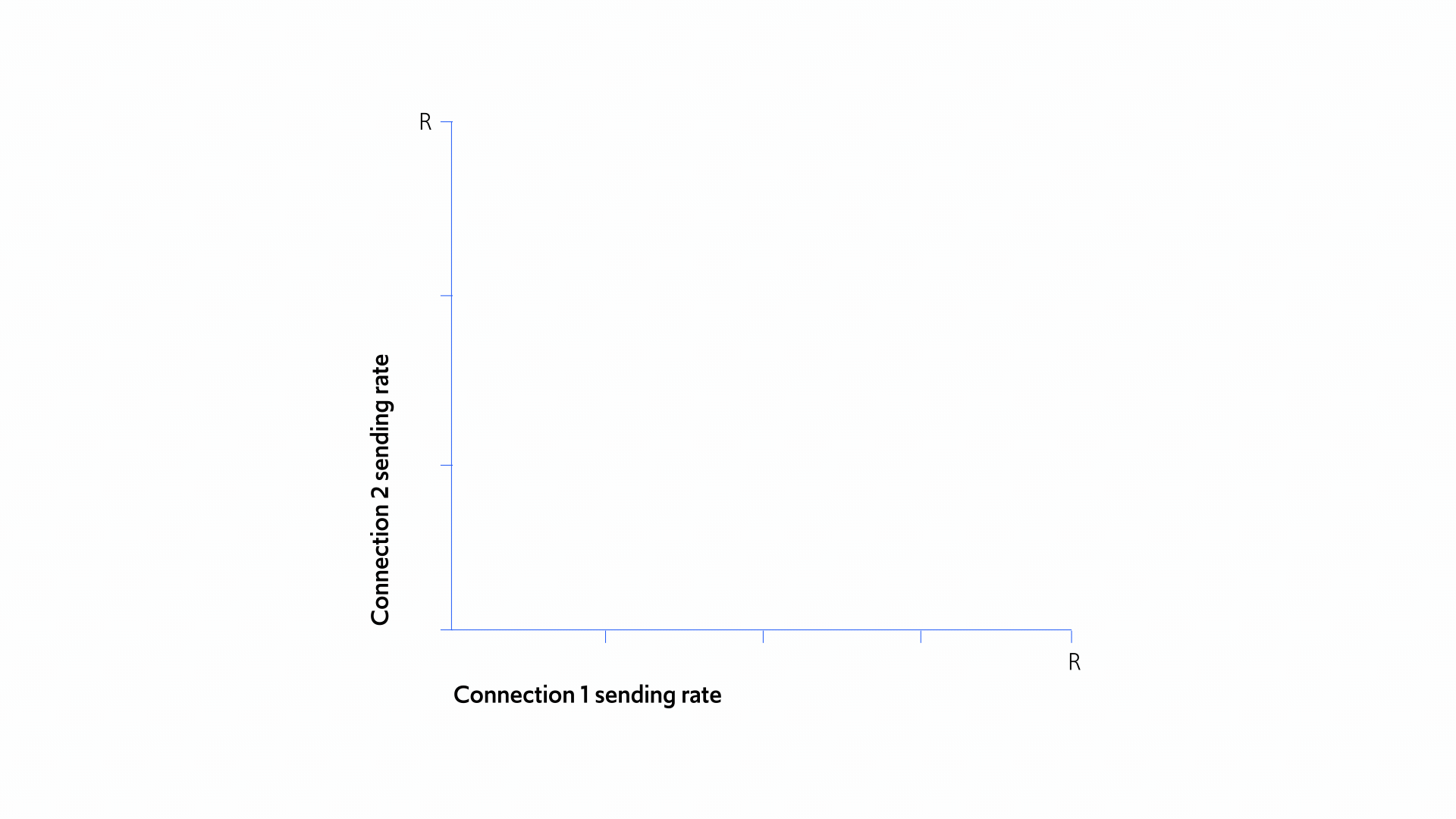
Figure 8: Perfect fairness for all parties sharing bandwidth
Figure 9: Combined sending rates fully utilize the link
Figure 10: Maximizing fairness and utilization
Adapted from http://gaia.cs.umass.edu/kurose-ross-ppt-6e/
When several flows interact, the sawtooth behavior of TCP gradually comes closer and closer to the line of fair bandwidth distribution, as you can see in Figure 11 below:
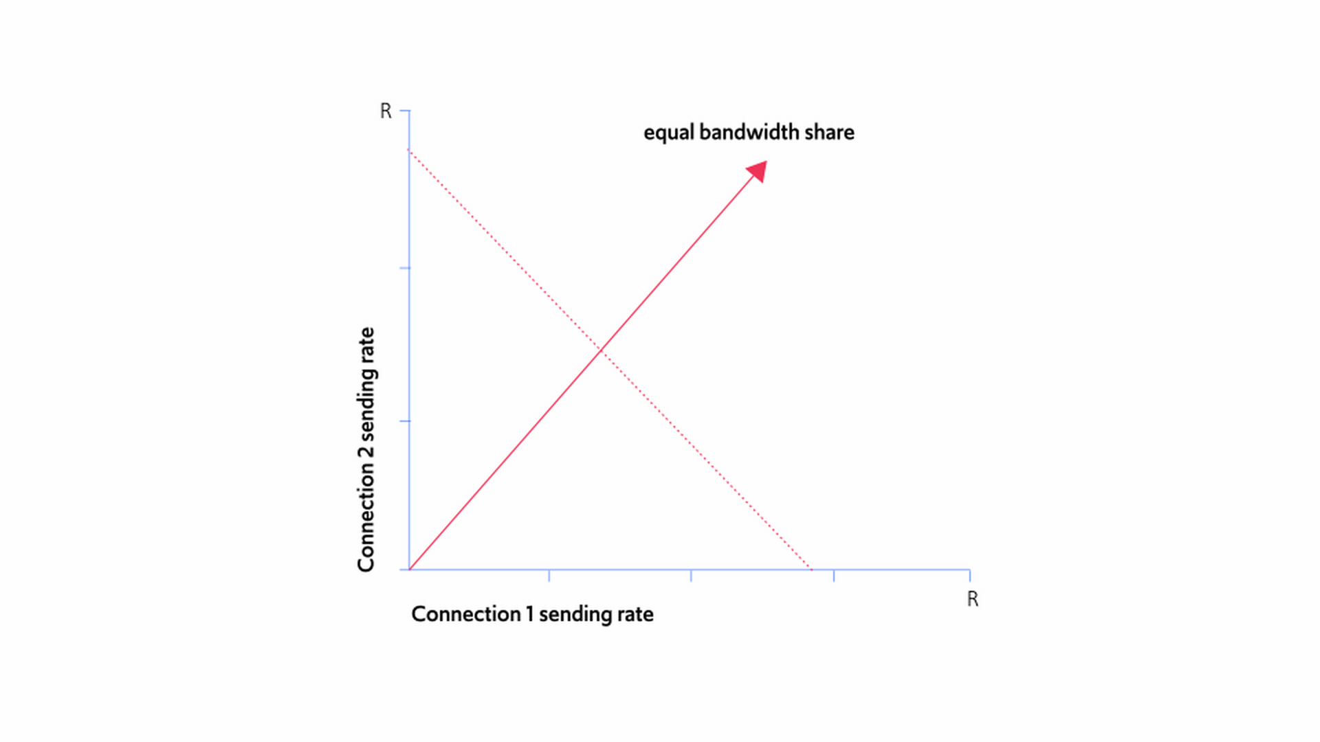
Figure 11: Finding the sweet spot for fairness and bandwidth sharing
Adapted from http://gaia.cs.umass.edu/kurose-ross-ppt-6e/
Figure 11 demonstrates the joint sending rates of the two senders in the following scenario. As can be seen in the figure, connection 1's sending rate is initially higher than connection 2's sending rate. Over time, each sender increases their rate in a linear fashion until their joint rates hit the R line of total link capacity. At this point they both start to see packet loss and drop their rates by half. The sender that had a higher traffic rate, namely, connection 1, therefore cuts its rate by more than the slower sender, resulting in the two connections' sending rates being closer to each other than previously. This linear increase followed by the halving of rates continues, each time bringing the two sending rates closer, and so better approximating a fair outcome.
This behavior, in which the senders get closer and closer to the fairness line, holds true no matter how many senders there are; senders with faster sending rates will always cut their rates by more than senders with slower rates (because half a faster rate is more than half of a slower rate), enabling senders with slower rates to eventually catch up.
The wide variety of TCP flavors
We have so far illustrated TCP by using TCP Reno as an example, but TCP comes in many different variants. Other types of TCP also have a slow start phase and a congestion-avoidance phase; and adapt the congestion window in response to receiving or not receiving ACKs. The differences between TCP variants lie in the manner in which the congestion window is adjusted, and typically focus on the congestion avoidance phase.

Figure 12: TCP Cubic behavior during congestion avoidance
TCP Cubic
One prominent example is TCP Cubic, which was proposed in 1998 and remains the dominant TCP in today’s networks. Cubic is the default congestion control algorithm for many operating systems, and specifically for Linux OS. TCP Cubic attempts to take over available bandwidth more quickly than TCP Reno, while still being fair towards other TCP connections. Like TCP Reno, Cubic also halves its congestion window when packet loss is detected in congestion avoidance mode.
The primary difference lies in how Cubic increases its rate during congestion avoidance. Suppose a TCP Cubic sender experiences packet loss when its congestion window size is W, and then cuts its congestion window in half. Intuitively, Cubic will initially increase its congestion window sharply, then gradually slow the growth of the congestion window as it approaches W, which is where it previously encountered a problem. If the congestion window exceeds W without seeing packet loss, Cubic gradually increases the growth of the congestion window. This concave-and-then-convex behavior mimics the graph of the cubic polynomial, hence the name. Figure 12 illustrates the change to the congestion window after the congestion window has been halved due to packet loss.
TCP Vegas
Another interesting TCP variant is TCP Vegas. Vegas is latency-sensitive, unlike both Reno and Cubic, which are purely loss-based. For loss-based congestion control algorithms, the packet RTT has no influence on the decision to increase or decrease the congestion window. In contrast, when Vegas is in congestion avoidance, it will decrease the window size not only after encountering packet loss as with loss-based TCP variants, but also when the RTT is “too long.” Vegas will also increase the window size only once it observes that RTT is “sufficiently low.”
Unlike Reno and Cubic, Vegas picks up on increased RTT while packets are waiting in network queues. As a result, it can keep packet delays low by dropping its rate when packets start aggregating within the network. While this sounds great in theory, it also gives rise to a major drawback. When TCP Vegas senders compete with TCP Reno or Cubic senders over the same links, the former always makes way for the latter. This is because Vegas senders start decreasing their rates at a much earlier stage, leaving themselves with a very small share of network bandwidth. Because Reno/Cubic senders are oblivious to increases in the packet delays captured by RTTs, they continue sending at full speed until seeing packet loss.
TCP variants for specific environments
Some TCP variants are optimized for specific environments, such as data centers, WiFi networks, and satellite networks. For example, round-trip time (RTT) for satellite data transmission may be many hundreds of milliseconds, which is a long time in internet terms. High RTT means it can take a long time before the sender receives any feedback about data packets. On top of that, satellite data transmission networks often experience non-negligible, non-congestion-related packet loss. Standard TCP assumes that any loss indicates congestion; but if the loss isn’t congestion related, the sender would cut traffic rates for no reason. So a different form of TCP for satellites, known as TCP Hybla, was invented to deal with these issues.
WiFi and mobile networks also commonly experience non-congestion-related loss, as well as other challenges such as frequent changes in bandwidth due to changes in signal strength or user mobility. This has encouraged researchers and practitioners to tailor solutions to these specific environments.
The relatively large number of different TCP variants demonstrates TCP’s algorithmic deficiencies, which require the design of different point solutions. While TCP has served the internet admirably well, it is notoriously bad for performance in many real-world environments.
We’ll now elaborate about the drawbacks and possible alternatives to TCP.
Section 5
Where TCP falls short
Where TCP falls short
TCP’s hardwired responses don’t always make sense
Every TCP variant has a hardwired response built into the solution. TCP is a rigid formula that produces a fixed response for packet level events. For example, whenever packet loss is detected, TCP responds the same way, without considering that different causes of packet loss may require different responses. Typically, this involves cutting the sending rate in half, as done in TCP Reno and Cubic.
TCP’s response reflects its underlying assumptions. Two strong, though implicit, assumptions regarding packet loss are:
-
Any packet loss is a sign of network congestion
-
The sender is always the one responsible for congestion
However, these assumptions are often violated in practice, as we explain below.
There are many possible reasons for packet loss, each requiring a different response. Even the same connection may suffer packet loss for different reasons at different times. Here are some possible scenarios:
Figure 13 shows the best response to each of the four scenarios described above.

Figure 13: Best response to different packet loss scenarios
In many cases, the hardwired TCP response is actually the opposite of the most effective response. For example, if the packet loss isn’t congestion-related, the sender should increase its sending rate, not cut it in half. The fundamental problem that makes TCP algorithms inefficient for congestion control is that any hardwired response to packet loss that does not take into account the cause or context will fail to provide high performance.
The decision to reduce traffic rates by half is purely arbitrary. Why by half and not by two-thirds or a quarter? There’s no real answer.
TCP is one-size-doesn’t-quite-fit-anyone
Another fundamental limitation of TCP is that you can’t customize it for the needs of different applications and network conditions.
Regardless of whether you’re watching VoD on your smart TV in Manhattan, or watching live sports on your mobile device in Barcelona, TCP (Cubic, by default) will operate in the exact same manner. It can’t accommodate the specific requirements of the different internet applications and services running on the network, nor can it customize its rate adjustment rules to network conditions.
Earlier, we gave the example of someone watching a movie on their mobile device while a software update is being downloaded in the background. Ideally, the time sensitive movie, which is the primary user, should be prioritized over the software download, which is termed a scavenger. But, if both applications use TCP Reno or TCP Cubic, that’s not what will happen. As we discussed in Section 4, Reno and Cubic will try to ensure that the two connections share network bandwidth (almost) equally. This might result in the streaming video getting less bandwidth than it needs to support HD viewing, while the software update downloads needlessly fast.
Different networks exhibit very different characteristics. Some networks may have plenty of non-congestion-related packet loss, which could be the case for the individual watching live sports on a mobile network in Barcelona. That’s because a mobile network connection is less stable, with frequent changes to the network bandwidth and subsequent loss rates. In other networks, all losses may be congestion related, which could be the case for the movie streamed over a smart TV in Manhattan. In some networks, competition for bandwidth can be fierce, while in others, the sender could be effectively isolated from other connections. In some, network buffers may be extremely deep, while in others they may be very shallow. Again, there is no reason to expect the same hardwired response to deliver high performance across such a broad variety of network environments.
With TCP, internet data delivery becomes one size doesn’t quite fit anyone. It is not customized to the needs of each user, application, or network. To address this, variants of TCP have been devised for specific network environments or specific applications, by tailoring the hardwired responses to specific contexts. However, the limitations of TCP’s algorithmic framework typically provide far-from-optimal performance, even in the environments for which they were designed.
Computer scientists have been exploring other types of congestion control algorithms that overcome these fundamental problems. Newer, non-TCP congestion control algorithms, such as BBR and PCC, take completely different approaches. These alternatives are based on gathering meaningful data and using it to determine the best course of action.
These alternatives to TCP can be roughly categorized into model-based and model-free approaches.
Section 6
Model-based vs. model-free alternatives to TCP
Model-based vs. model-free alternatives to TCP
If you set out to design a new congestion control algorithm for environments like last mile networks, it will be tough to fully characterize all the network conditions the algorithm will encounter. That being the case, congestion control algorithm designers have to decide what they can reasonably assume about the network and which parameters they can confidently infer from their observations.
There are two main types of alternatives to TCP: model-based algorithms and model-free algorithms. The fundamental distinction between them is whether or not they are based on assumptions regarding the network and how it behaves.
Network-model-based algorithms rely on a representation of the network environment, that is, a model of the network. The model is based on both assumptions and on inferences from observed network dynamics. The algorithm uses the model to predict how network dynamics evolve and the ways that different sending rates will impact performance.
Network-model-free algorithms treat the network as a black box that cannot be accurately modeled. Without any basis for predictions, a model-free algorithm observes the performance that results from different send rates, and looks for empirically “good” mappings between rates and performance.
These two types of algorithms have different strengths. If you’re confident that your assumptions and inferences are correct, then a model-based algorithm will bring you to an efficient sending rate far faster than the experimental approach of a model-free algorithm. But if your assumptions are faulty, you’ll experience a lot of frustration trying to hit on the best sending rate for a murky network.
Imagine a single connection alone on a link with a total bandwidth of 100 Mbps. The best sending rate would be 100 Mbps. A model-based algorithm that has an accurate model would begin at 100 Mbps and thus reach the optimal sending rate almost instantly. But that only happens if it has an accurate model. What if the model is incorrect because the bandwidth is really 200 Mbps or the sender is not alone on the link? The algorithm will either fail to fully utilize the link, or it will send traffic too fast and cause packet loss. In contrast, a model-free approach might spend valuable time exploring the implications for performance of different send rates. But, if the model-based approach has the wrong model, the model-free algorithm is likely to outperform the model-based one, since it does not need to correct for a wrong model of reality.
Model-based approaches are well-suited for predictable networks where it’s possible to begin with an accurate model of the network. Some examples of these are the private intranets within large organizations such as Google, Facebook, and Amazon. These networks are stable and well-behaved; all the infrastructure of the network is under centralized control.
Model-free approaches are best for complex network environments that are hard to accurately model, and are inherently more robust in dynamic conditions. In the last mile of the internet, conditions are constantly changing (as we discussed above), so model-free algorithms are usually more appropriate.
We’re going to examine two options for congestion control in more depth. BBR is the archetypal white-box, model-based approach, originally developed by Google for its internal networks. PCC is the paradigm of a black-box, model-free approach, and is the basis for Compira Labs’ solution.
Section 7
BBR - A white box, model-based approach to congestion control
BBR - A white box, model-based approach to congestion control
BBR, short for Bottleneck Bandwidth and RTT, is one of the most well-known alternatives to TCP. BBR is a congestion control algorithm used to deliver YouTube traffic. It’s also been adopted by Netflix and some other important players.
The beauty of simplicity
BBR is quite simple at heart. Here’s the basic structure of the algorithm.
Imagine that one sender is sending data to another communication end-point. Somewhere along the route, the data hits a bottleneck link. Although traffic may be traversing a very complex network with multiple segments and varying competition, what matters for BBR is the bandwidth at the path’s narrowest point. We don’t know what’s causing the bottleneck; it could be increased competition from other traffic flows, low bandwidth, or multiple other issues. BBR models the entire network by boiling the whole journey down to a single link that’s the width of the bottleneck. It probes the network to infer bottleneck bandwidth and then adjusts its sending rate to match this bandwidth. We explain how BBR does this below.
How does BBR work?
To determine the bottleneck link bandwidth, BBR continuously examines its sending rate relative to the rate at which data packets arrive at the receiver. Consider a sender alone on a link with a bandwidth of 100 Mbps. Now, suppose the link is not congested. In this scenario, packets should arrive at the end-point at about the same rate at which they leave the sender; this means ACKs will also arrive at the sender at roughly the same rate. In our example, if the send rate is 50 Mbps, ACKs should also arrive at 50 Mbps. But, if the send rate exceeds the bandwidth and the link is saturated, traffic will arrive at the receiver at the same rate as the bandwidth since that’s the fastest rate the link can support. ACKs should also arrive at the sender at roughly that rate, which is 100 Mbps in our example. If the send rate remains above the bandwidth, queues will start to form as packets line up for delivery. By comparing the send rate to the ACK arrival rate, BBR can tell whether or not its rate has exceeded the link bandwidth, and estimate what that bandwidth is. BBR’s estimated bottleneck bandwidth is the optimal operating point for BBR. It’s fully utilizing the link without exceeding bandwidth, so loss and latency are kept to a minimum.
To see how BBR chooses when and how to increase/decrease its send rate, let’s stick with our simple example of a single sender on a 100 Mbps link. Like TCP, BBR begins in slow start mode, doubling its rate every RTT. This goes on until the send rate has exceeded the estimated bottleneck bandwidth. When that happens, BBR drops its rate to match the estimated bandwidth and enters congestion avoidance mode. BBR periodically increases its rate by 25% to check whether the bottleneck bandwidth has changed. If the receiving rate rises in tandem, BBR knows it can continue at this higher rate. If the receiving rate doesn’t rise with the increased send rate, packets are clearly being sent at a higher rate than the network can support. This means there’s a line of packets waiting in the buffer, which can cause packet loss or excessive delays. To address this, BBR regularly drains the queue by dropping send rates to 25% below the previous norm, so the buffered packets can be sent without any more piling up. If we drew a graph of the send rate for the BBR sender in our example, it would look something like this:

Figure 14: BBR send rates with one sender on the link
Adapted from Figure 7 in https://blog.apnic.net/2017/05/09/bbr-new-kid-tcp-block/
Although our example is for a network path made up of a single link, BBR models the entire path as a single link no matter how many links actually comprise the path. For this reason, BBR uses the same process to estimate bandwidth in every scenario. When multiple, long-lasting BBR connections send traffic across the same link, experiments show that they usually each get their fair share of bandwidth.
BBR vs. TCP
BBR differs from TCP on two main points:
-
BBR adjusts the sending rate, not the congestion window. We already explained that TCP changes the congestion window rather than the actual send rate. For BBR, decisions are made about the speed of traffic in Mbps.
-
BBR gathers meaningful statistics. Unlike TCP, BBR does not prescribe a hardwired reaction to packet level events. Instead, it attempts to infer meaningful statistics about the network, mainly through the ACK receiving rate, and build upon them to guide its rate selection.
BBR outperforms widespread TCP variants such as TCP Cubic under most circumstances. By explicitly targeting the bottleneck bandwidth, BBR achieves better throughput and lower latency. In addition, BBR is inherently more resilient to non-congestion-related loss because, unlike TCP, it doesn’t treat packet loss as a congestion signal.
That said, BBR does have drawbacks.
When is BBR not a good fit?
BBR relies on its ability to model the network, in all its complexity, in a manner that is both tractable and useful for decision making. Not surprisingly, this isn’t always possible, especially in the chaotic last mile.
Although BBR seems to have a good model of the situation, the network can still contain surprises. Competing traffic flows enter and leave abruptly; the underlying routes might change; different senders may share links with connections that employ different congestion control algorithms; user mobility may cause unexpected packet loss and bandwidth fluctuations; and more.
When the BBR model deviates too far from reality, BBR makes ill-informed decisions.
Another serious drawback is that BBR is not a “fair” congestion control solution. BBR typically works fine with traffic sources that use the same protocol. But when BBR goes up against other traffic control protocols, it doesn’t play nice. BBR can be very aggressive towards other traffic flows, taking over all the limited available bandwidth.
Section 8
PCC - A black box, model-free approach
PCC - A black box, model-free approach
PCC, short for Performance-oriented Congestion Control, was developed jointly by researchers at the Hebrew University of Jerusalem and the University of Illinois at Urbana Champaign (UIUC). Like TCP, and unlike BBR, PCC is a general framework for congestion control algorithms. All PCC variants are built using the same general architecture of utility function and online rate selection, as we’ll discuss in more detail below. PCC variants differ in the specific choice of utility function and online rate selection scheme built into the congestion control algorithm.
The significance of being “model-free”
As we explained, BBR is a model-based, white-box approach that draws on network statistics to make inferences about network conditions. PCC is the polar opposite. It approaches the network as a black box that cannot be understood. PCC senders never try to infer network parameters, such as the bottleneck bandwidth or the root cause for packet loss.
Instead, PCC regards data transmission as a series of “micro-experiments.” In each such micro-experiment, the sender quantifies the level of performance for the current rate of sending. It uses this information to adjust its send rate over time.
How does PCC work?
PCC has two main components:
-
Utility function
-
Online rate selection algorithm
The utility function, or utility framework, takes statistics that result from the selected send rate and translates them into a performance score, or utility value. This utility value represents the level of performance achieved by sending at that rate. The online rate selection algorithm decides what rate to choose next, based on the utility values observed for the previously chosen send rates.
PCC utility framework: the advantages of flexibility
When a PCC sender begins sending packets of data at a certain rate, it starts to receive ACKs after an RTT. These ACKs can reveal information, including what fraction of packets were lost, the rise or fall in packet delays, etc. The PCC sender collects this information and aggregates it into a utility value, or performance score.
Let’s consider the scenario in which performance for a certain send rate is measured as the portion of traffic that safely reaches its destination. Imagine a simplified connection with a sender sending packets at 50 Mbps, where 30% of the packets, or 30 out of every 100 sent, get lost on the way; this means that 70% arrive. When using this simple utility function to quantify performance, the derived utility value equals 35, which is 70% of the 50 Mbps.
This utility function can be expressed by the following equation:
U = X(1-L)
where:
-
X is the send rate
-
L is the fraction of packets lost; e.g., L=0 means no packets are lost, L=0.1 means 10% of the packets are lost; L=0.5 means 50% of the packets are lost; L=1 means that all packets are lost, etc.
-
U is the performance score
For example, if no packets are lost, then X and U are the same, since all packets arrived at the destination. If half the packets are lost, then U=X/2.
This specific choice of utility function is too simple to be effective. Here’s why:
-
If you send at 100 Mbps without any packet loss, U would equal 100.
-
If you send at a rate of 200 Mbps and see 50% packet loss, U still equals 100.
U is the same in both cases, even though it’s obviously better to have no packet loss than to lose half your packets—without gaining anything in terms of throughput.
The utility function in this example completely ignores latency. It only reacts to congestion once the network buffers are exhausted and packets are dropped, instead of responding to the onset of congestion.
Fortunately, we can create better utility functions by setting a penalty for packet delays and packet loss to induce desired properties. The penalty for packet delay is expressed as pD, and the penalty for packet loss is expressed as pL. Such utility functions have the following general form:
U = X - pDX - pLX
As before, X is the send rate, L is the fraction of packets lost, and U is the performance score. The penalties for both packet delay and packet loss should increase as the delays and losses increase. Therefore, pL and pD can take many different forms. For instance, when setting pL=100L the negative impact of packet loss on the sender’s utility value is 100x higher than when setting pL=L. Observe that when we set pD=0, so there is no penalty for packet delays, and pD=L, we get
U = X - L x X = X(1-L)
This is precisely our simple utility function from before.
Now the equation includes three factors that need to be taken into consideration:
-
Send rate (X), which we want to push as high as possible
-
Packet delays (penalized by pD), which we want to keep as low as possible
-
Packet loss (penalized by pL), which we also want to keep as low as possible
Identifying good choices for utility functions can be delicate, since the utility function has two important roles:
1. Flexibility to customize performance for different apps
As we mentioned above, different apps have different needs. Some of them are latency sensitive, like Zoom, while others are bandwidth-hungry, like Netflix. The utility function can be adjusted to match the needs of each app. For example, when using PCC for Zoom, we could set the penalty for packet delays to be higher than when using PCC for Netflix. This would result in behavior that is more oriented towards minimizing latency, as favored by Zoom, even if this comes at the expense of lower bandwidth utilization, which is more crucial to Netflix.
2. Ensuring fairness between connections
We already discussed the importance of fairness for congestion control solutions. With PCC, each sender is focused on optimizing its own sending rate according to its utility function. Consequently, there’s a risk that one sender could monopolize all the bandwidth, starving the other connections. The reason they reach a fair equilibrium rests on game theory. As long as PCC users are homogeneous and all using utility functions from a certain family, they are guaranteed to share bandwidth equitably. Desirable bandwidth distribution can also be guaranteed in other important scenarios.
For example, this can be accomplished by using one class of utility functions for primary, time-sensitive traffic such as video conferencing, and another class for “scavenger” traffic such as software updates.
PCC online rate selection
After the utility function, the second component of PCC is the online rate selection algorithm. A PCC sender needs to decide what send rate to use next, based on the utility values it observes for previously chosen rates. This is the role of PCC’s online rate selection algorithm.
Here’s how it works. Just like TCP and BBR, PCC begins in slow start mode and doubles its rate every RTT. This continues until the utility score stops rising; this indicates that PCC increased the rate by too much and consequently experienced a drop in performance. At this point, PCC enters congestion-avoidance mode.
Now, imagine that PCC is sending at a certain rate r. A simple way of figuring out whether it should increase or decrease its rate is the following. PCC can send at a slightly higher rate of 2% above r and examine the derived utility value, and then send at a slightly lower rate of 2% below r, and again examine the derived utility. After evaluating how sending at higher and lower rates impacts performance (i.e., the utility value), PCC can then switch to the lower or higher rate, depending on which produced the highest performance score.
No reverse engineering needed
This algorithm for adapting send rates was used by the earliest variant of PCC, called PCC Allegro. Although quite simple, it avoids some of TCP’s deficiencies. Consider the scenario in which the sender experiences packet loss that is not congestion-related. For instance, suppose, that 1 packet out of every 100 is dropped, regardless of how fast you send data. Here, raising the send rate will not increase the fraction of packets lost, but will result in more packets getting across to the receiver and a better performance score. PCC Allegro will thus choose to increase its rate. In contrast, if the sender experiences packet loss that is the result of congestion, increasing the rate will only induce more packet loss while not getting more traffic through, leading to worse performance. Here, PCC Allegro will therefore choose to decrease its rate. Recall that TCP would reduce its send rate regardless of the cause of packet loss, as discussed in Section 5. As you can see, PCC Allegro is capable of effectively distinguishing between two different causes of packet loss and reacting in a different manner to each.
Unlike BBR, the PCC algorithms don’t try to determine why a higher rate is better than a lower rate, or vice versa. The sender doesn’t try to reverse engineer the network conditions, say by explicitly reasoning about the possible cause of experienced packet loss. Instead, the sender treats the network as a black box and merely tries to learn which changes to its current rate will induce the best performance.
Improving over PCC Allegro
Although PCC Allegro’s simple algorithm is effective, it still has some drawbacks. The primary difficulty is that it always changes its rate by a fixed step size. In our example, that was 2%. As we will discuss below, in some situations, this step size will be too big and in others it will be too small.
For example, Figure 15 below shows a PCC algorithm that decreases the sending rate in small steps of 1%. Suppose that the sender is initially sending at a rate of r, which is much higher than the network bandwidth R. Since the sending rate is significantly higher than what the network can support, there will be a lot of packet loss and/or packet delay. These losses and delays will continue while the rate slowly drops in tiny increments, until it reaches the bandwidth threshold again. Alternatively, if the current send rate is well below the available bandwidth, raising the sending rate one 1% step at a time might take too long to reach decent bandwidth utilization.

Figure 15: PCC algorithm decreasing in small steps of 1%
On the other hand, Figure 16 shows what can happen if the step size is fixed at a value that is too high, like 30%. Consider first the scenario depicted in Figure 16(a), in which a connection is sending on a link at a rate of r1, which is much lower than the available bandwidth, R. This leads to poor network utilization, so the PCC algorithm will increase its rate. Since the step size is large, the sender will increase its rate in a single huge jump, and is likely to massively overshoot network capacity, as in the figure. Then, to recover from this mistake, it will decrease its rate to be too low, as in Figure 16(b), then increase it again, and so on.

Figure 16: Large PCC step size for increase or decrease
More advanced PCC rate control schemes build on the rich body of literature in machine learning and game theory to address this issue. PCC Vivace is one example of a scheme that is far more responsive to network change and has a better convergence rate than PCC Allegro.
The benefits of a model-free approach
As we discussed above, congestion control solutions that rely on strong assumptions about the network, like TCP and BBR, can easily lead to poor performance when their models of the network deviate from reality. Thanks to its model-free approach, which avoids making any assumptions, PCC is far more robust in responding to unexpected changes in network conditions. These changes are a fact of life in real-world environments, especially in the last mile.
In a simple controlled experiment, we compared BBR and PCC in circumstances that reflect the unpredictable changes in the chaotic last mile. We had the latency, available bandwidth, and packet loss varying every second. The graph below shows the effects on PCC and BBR, as well as the ideal bandwidth utilization. On the graph:
-
The dotted line shows the optimal send rate that fully utilizes the available bandwidth without causing packet losses and delays
-
The dot-dashed line shows PCC delivery
-
The plain line shows BBR delivery

Figure 17: Comparing BBR and PCC performance in a chaotic network environment
You can see the gap between PCC and BBR’s performance due to the chaotic nature of the network. PCC mirrors the peaks and troughs of the optimal line far more closely than the BBR rate.
Conclusion
The exciting future of congestion control
The exciting future of congestion control
As you now understand, congestion control has been a challenge for decades. Computer scientists attempting to solve it need to overcome a number of obstacles, including murky, ever-changing last mile conditions; ongoing competition from other connections; the need to balance bandwidth utilization with minimal packet loss and delay; and the requirement to be fair across connections; amongst other issues.
It’s an exciting time for internet data delivery, with new solutions hovering within reach. For the first time in a very long time, the TCP paradigm is being contested and other schemes -- such as BBR and PCC -- are already being deployed. As more and more of our lives move online, the need for high quality and fair network access will only grow. We’re already seeing an increasing need among both businesses and consumers for applications such as streaming video, video conferencing, eSports, live online religious services, socially distant choirs, and more. Today, we need more effective ways to improve internet quality of experience. And congestion control is a crucial element for service providers to consider.
About the Author
Michael Schapira, PhD is the Co-founder and Chief Scientist of Compira Labs, and is the co-author of the research on internet congestion control that led to the creation of the company. He is also a professor of computer science and co-leads the Fraunhofer Cybersecurity Center at the Hebrew University of Jerusalem. Michael has held research positions at Google, Princeton, Yale, and UC Berkeley. He has authored over 100 research papers and is the recipient of multiple awards, including ones from Microsoft, Google, Facebook, the Wolf Foundation, and the IETF.
About Compira Labs
Compira Labs is a pioneer in personalizing content delivery. Building on groundbreaking academic research, the company’s technology applies machine learning and game theory to last-mile Internet data delivery, dramatically improving user experience for latency-sensitive and bandwidth-hungry Internet services ranging from Over-The-Top (OTT) video streaming and esports to Cloud Gaming and 5G applications. Compira Labs’ software-only solution is deployed at the edge of the network and has been selected by leading service providers worldwide to ensure that their customers enjoy unmatched user experience.
Acknowledgements
I thank Brighten Godfrey, my long-time collaborator on PCC, Amit Cohen and Lev Gloukhenki from Compira Labs, and also Scott Shenker and Keith Winstein, for insightful discussions about congestion control that have profoundly impacted my views on this topic. I am also grateful to Rebecca Herson, without whom the creation of this ebook would not have been possible. I would also like to thank Amanda Bradley and Chani Sacharen for their valuable comments and suggestions.
